
Configure a Trimble GNSS receiver through its web interface so it can supply position data to Hovermap for RTK scanning. Complete the Trimble hardware setup before starting.
What you will need
Hovermap unit with a Vehicle RTK or Backpack RTK mount and a Trimble GNSS receiver, configured as described in Vehicle RTK or Backpack RTK
Access to a web browser.
RTK base station (optional).
Configure the receiver through the Trimble web interface rather than the Trimble controllers, to avoid overriding the receiver's settings.
Procedure
Step 1: Connect to the Trimble receiver
Turn on the Trimble receiver, then connect to its Wi-Fi network.
In a web browser, enter 192.168.142.1 in the address bar to open the Trimble web interface.
Enter the login credentials on the Login page.
The default username is admin and the default password is password.
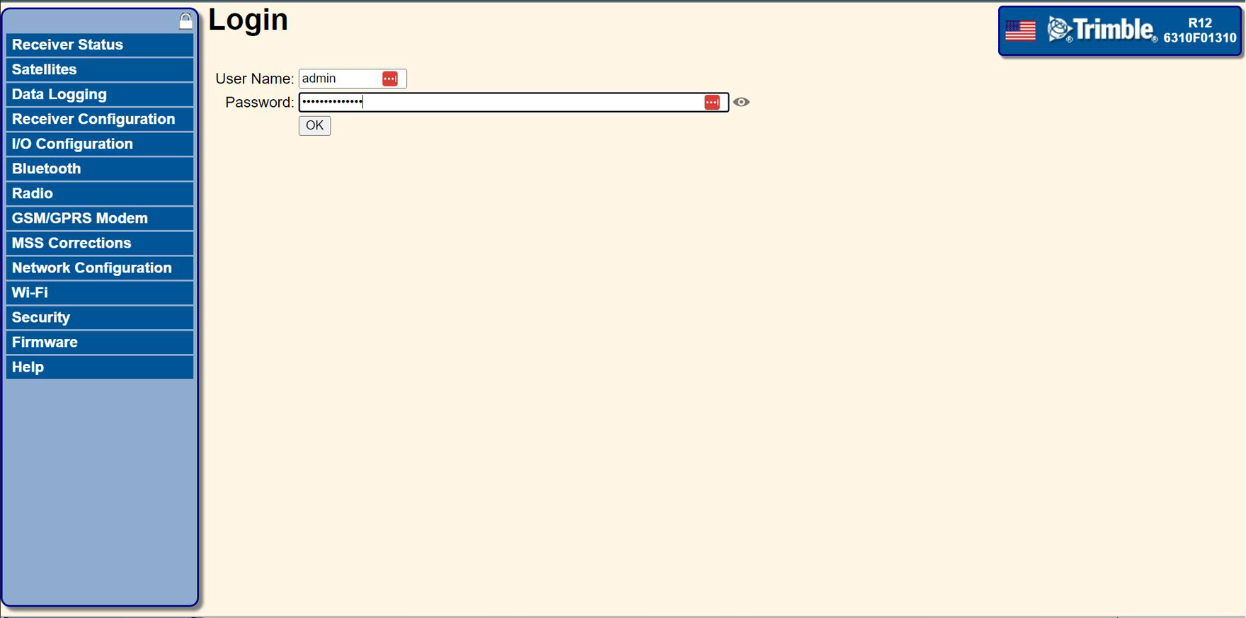
Figure 1. The Trimble web interface Login page.
Step 2: Check the NMEA installation
Confirm that the NMEA option is installed.
Go to Receiver Status > Receiver Options in the left panel. The Options panel appears on the right.
In the Options column, find NMEA. Confirm that an X appears next to it in the Installed column.
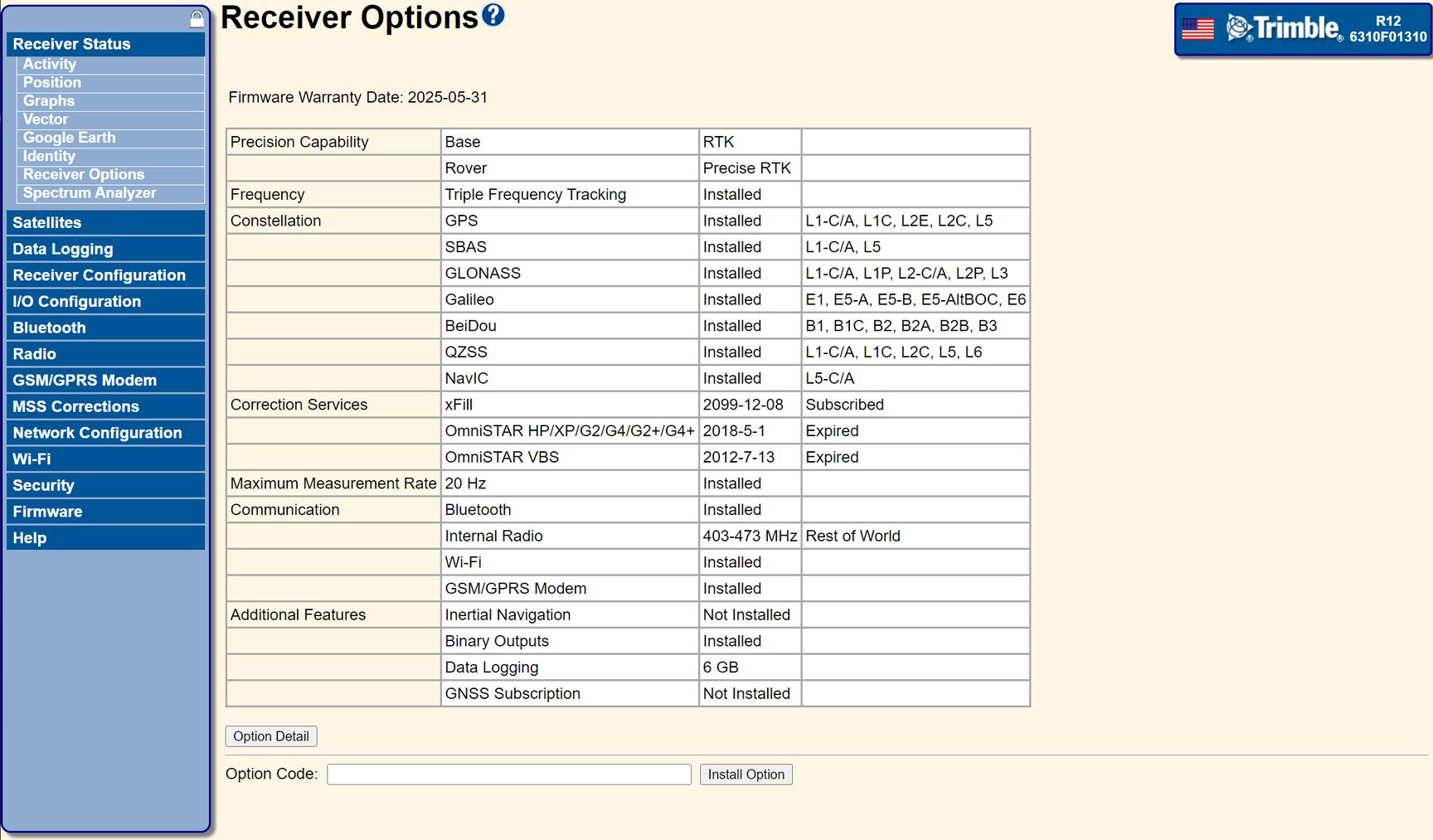
Figure 2. The Receiver Options page with NMEA installed.
Step 3: Configure the NMEA settings
Configure the NMEA output settings so the receiver can communicate with Hovermap.
Go to I/O Configuration > Port Summary in the left panel. On the right, click Configure for the port assigned to the RS-232 Port 1 connection.
Set Input to None and Output to NMEA.
Under Serial Port Setup, configure the settings in the table below.
In the Input/Output section, set the output rate for each message in the second table below.
Setting | Value |
|---|---|
Baud | 115200 |
Parity | N |
Flow | Disabled |
Message | Rate |
|---|---|
GGA | 5 Hz |
GSA | 5 Hz |
GST | 5 Hz |
ZDA | 5 Hz |
GSV | 1 Hz |
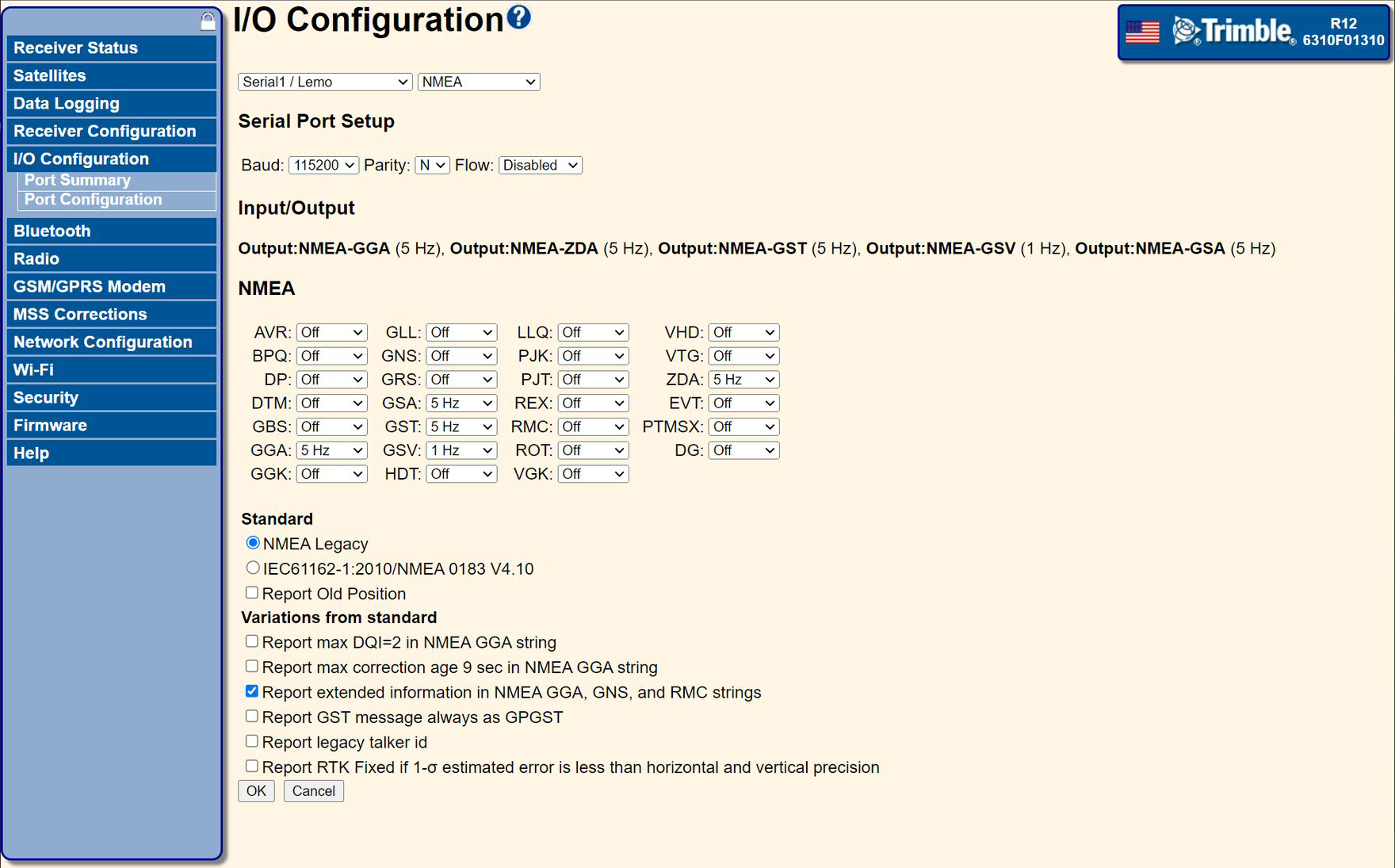
Figure 3. The NMEA message output rates.
Click OK to save the port configuration.
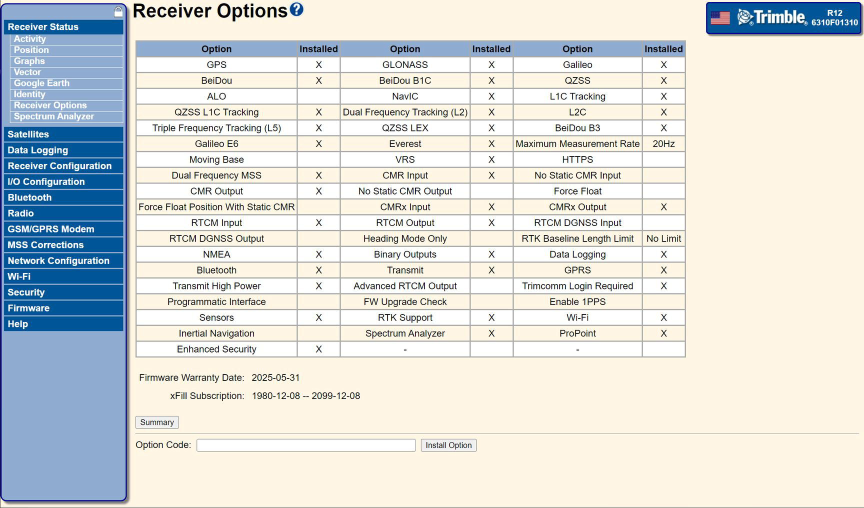
Figure 4. The Port Summary page for the configured RS-232 port.
Step 4: Configure the tilt and antenna height
Hovermap cannot detect an incorrectly set antenna height, so ensure it is configured correctly.
Go to Receiver Configuration > Antenna in the left panel.
In the right panel, configure the following settings.
Setting | Value |
|---|---|
Antenna Measurement Method | Antenna Phase Centre |
Antenna Height | 0.000 |
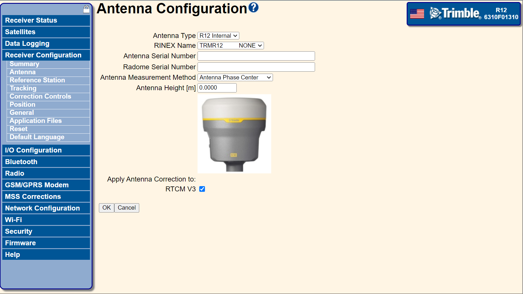
Figure 5. The Antenna configuration settings.
Using tilt compensation
If the antenna height is set to 0.000, tilt compensation does not apply. Even so, disable tilt compensation for best performance: go to Receiver Configuration > INS, clear the INS Enable option, then click OK to save.
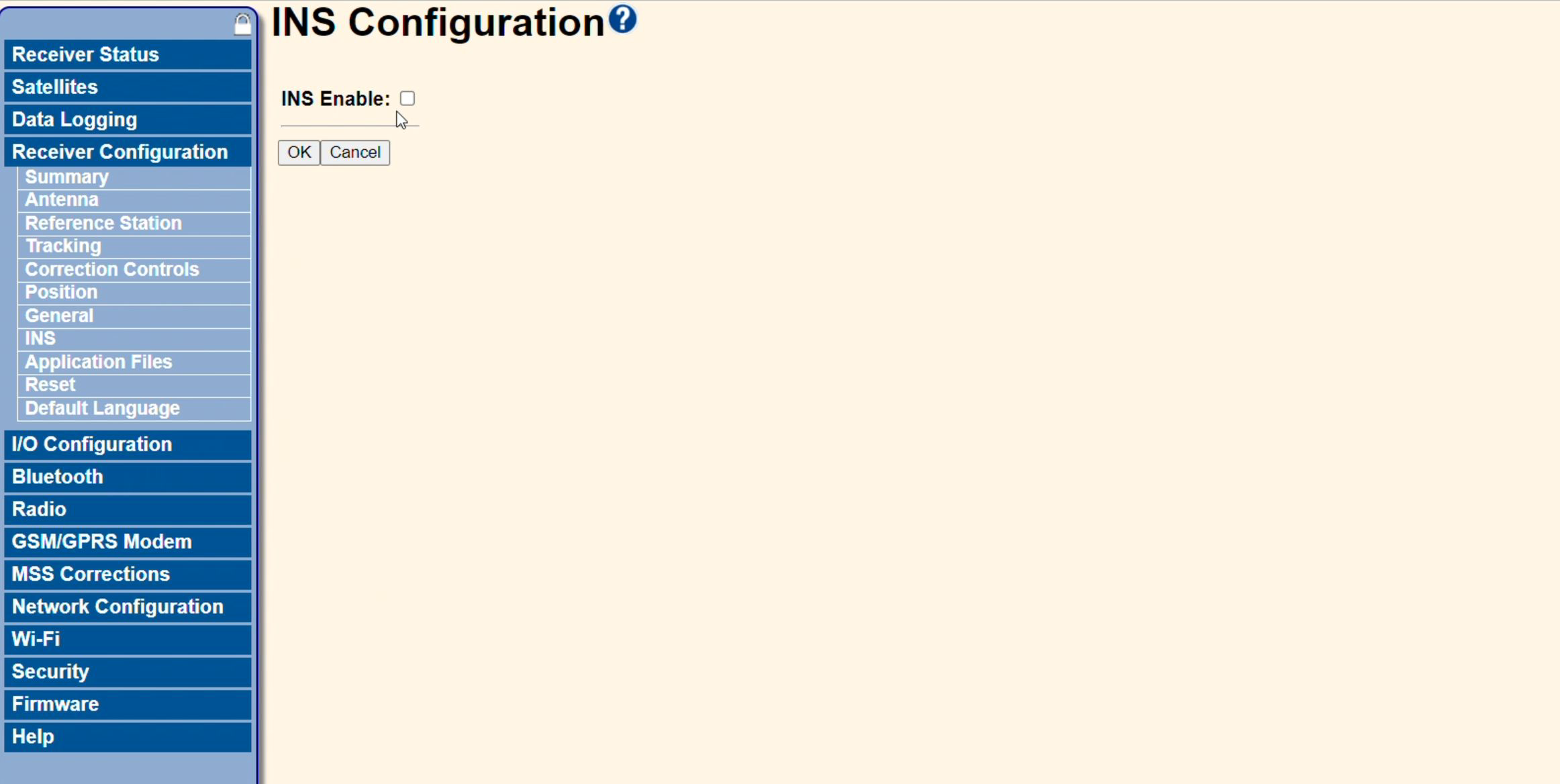
Figure 6. The INS page, where tilt compensation is disabled.
Receiver motion profile
If the Trimble receiver is mounted on a vehicle, set Receiver Motion to Kinematic or another appropriate model for best results. This setting is under Receiver Configuration > Position. Click OK to save.
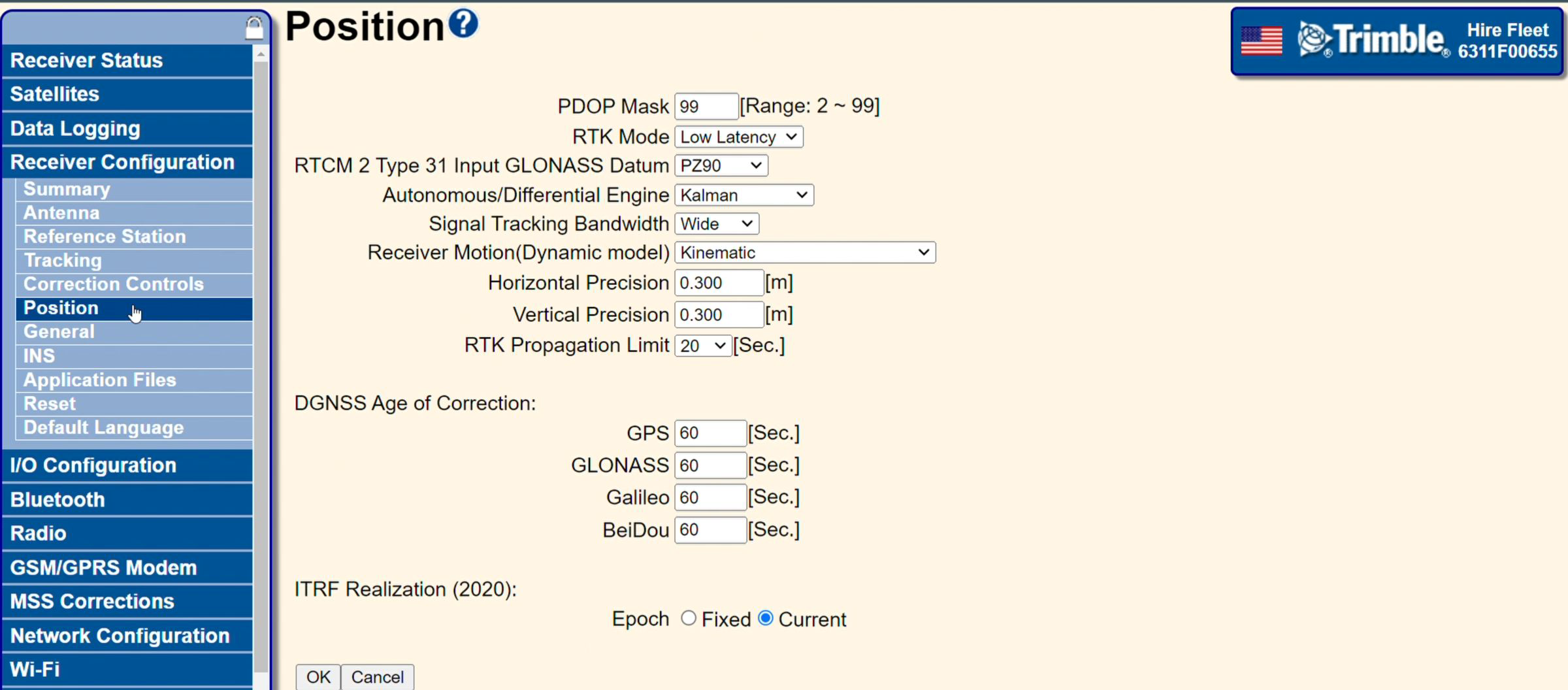
Figure 7. The Receiver Motion setting under Receiver Configuration > Position.
Outcome
The Trimble receiver is now configured for use with Hovermap and ready to capture RTK scan data.