
This article explains how to install the Hovermap Spot Cage on a Boston Dynamics Spot quadruped, attach the Hovermap payload to the cage, and (optionally) install the GXP Riser and Long Range Radio Antenna Extension Kit.
Installation involves three main tasks:
Install the Spot Cage on the robot and attach the Hovermap payload.
(Optional) Install the GXP Riser if a rear-mounted Boston Dynamics payload is also being used.
(Optional) Install the Long Range Radio Antenna Extension Kit for extended communication range.
What you will need
A Boston Dynamics Spot robot.
The Hovermap Spot Cage kit, including the alignment plate, T-slot nuts, M5 screws, and washers.
The Hovermap payload.
A Boston Dynamics GXP unit (with Shielded Ribbon Cable if using the GXP Riser).
The Fischer-to-Fischer cable, M12-to-HD15 cable, and M12-to-Ethernet cable supplied with the Spot Cage.
Optional: Emesent GXP Riser Kit.
Optional: Long Range Radio Antenna Extension Kit (matched to the LRR frequency band).
2 mm Hex Key, 8 mm spanner or adjustable wrench, and Loctite 222.
Procedure
Step 1: Prepare the robot and install the alignment plate
Remove any T-slot nuts in the payload rails that might block the installation of the cage.
Remove the alignment plate from the bottom of the cage as shipped, and set aside the attached M5 screws, washers, and T-slot nuts for later use.
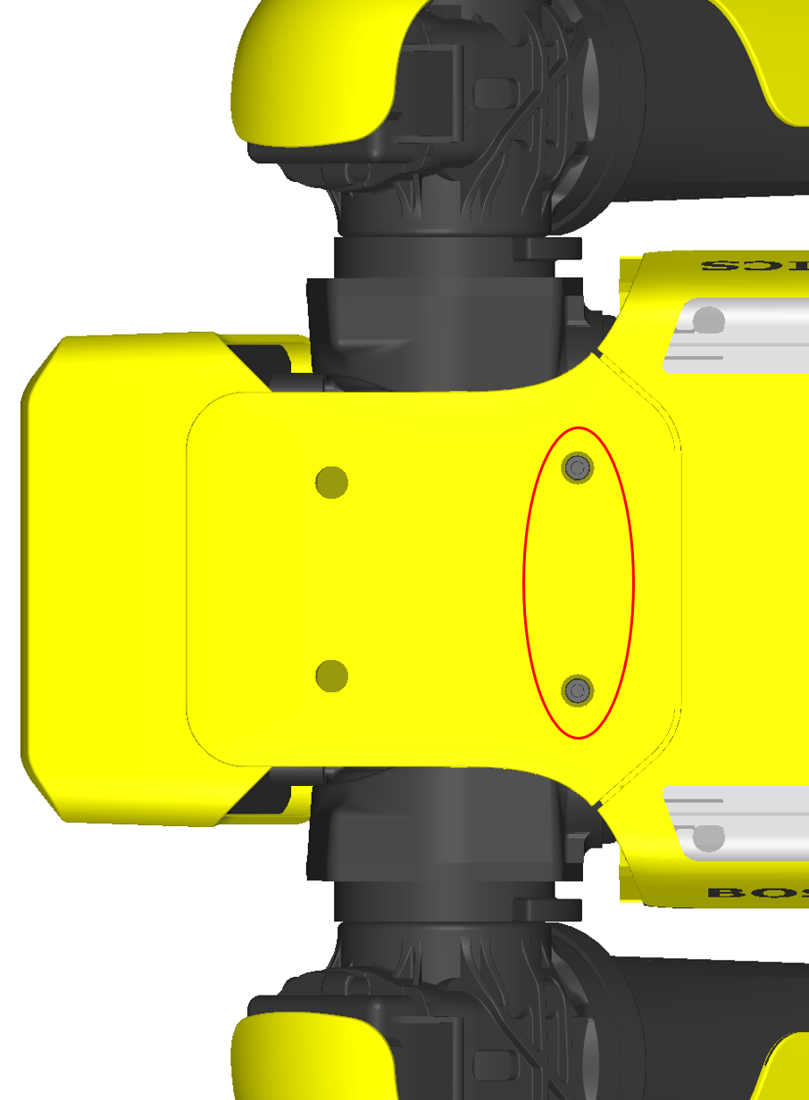
Remove the two M5 socket head screws from the arm mount at the front of the robot's body.
Insert four T-slot nuts into each payload rail (eight nuts total).
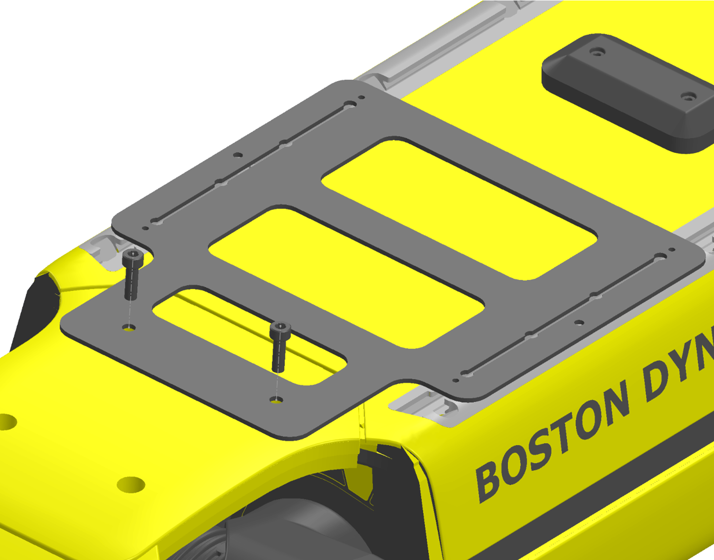
Install the alignment plate onto the robot using the two M5 socket head screws as shown. The alignment plate serves as a reference point for positioning all T-slot nuts within the payload rails.
Step 2: Align and secure the T-slot nuts
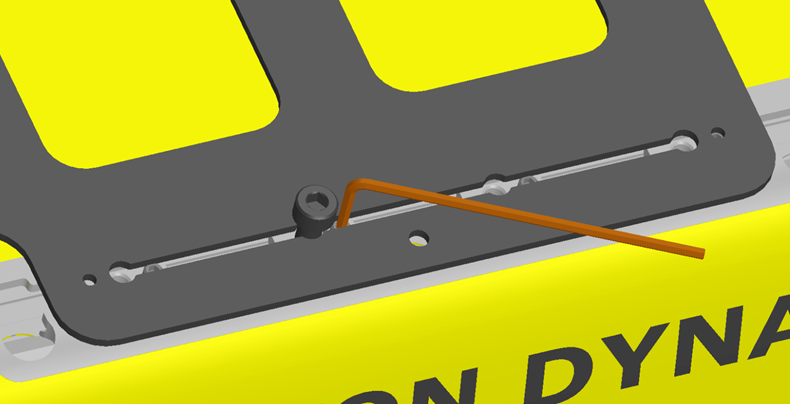
Position the T-slot nuts in the payload rails to match the cut-outs on the alignment plate. Use the elongated slot and a 2 mm Hex Key to slide them into position. Secure each nut in place by threading an M5 cap head screw, ensuring the nuts align with the designated holes.
Secure the eight T-slot nuts by tightening the set screws using the 2 mm Hex Key.
Step 3: Attach the cage to the robot
Remove the alignment plate by unfastening the two front M5 screws.
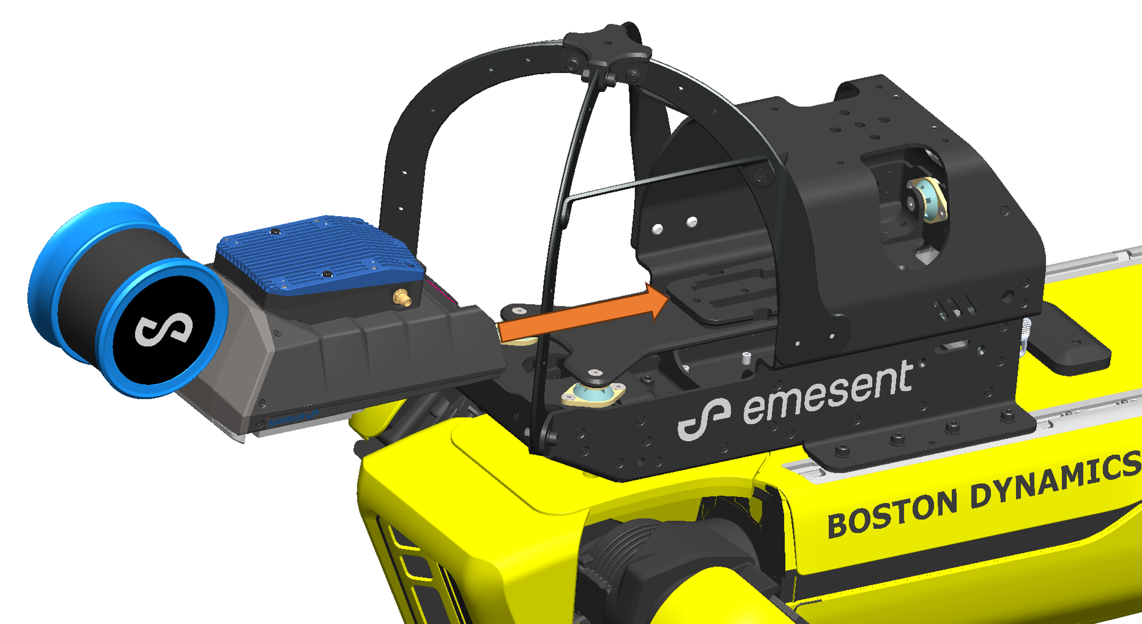
Position the cage on top of the robot and align the screw holes on the cage with the set T-slot nuts in the payload rails.
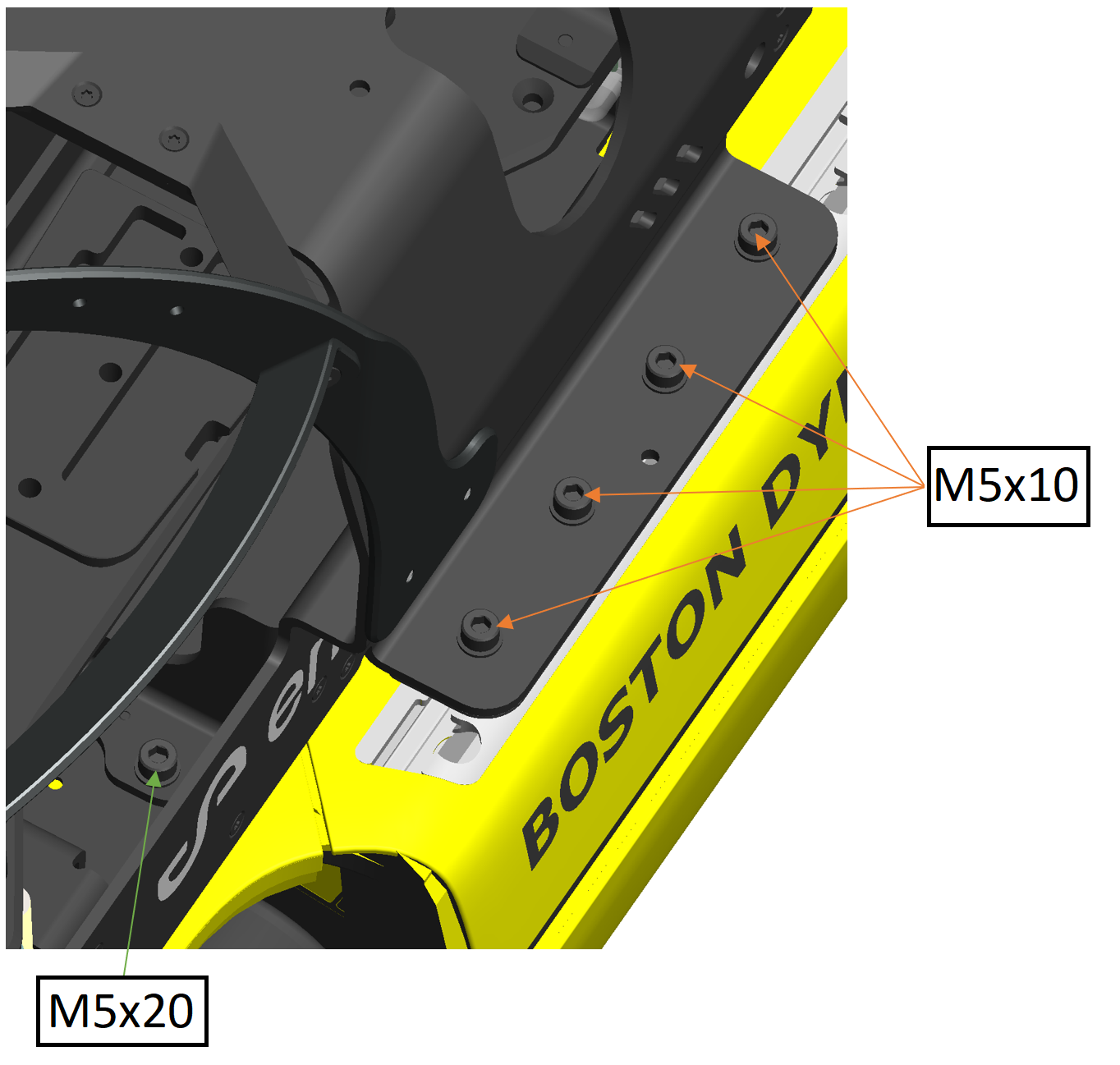
Secure the cage to the robot by fastening ten M5 screws, with one M5 washer underneath the head of each screw:
Insert eight M5x10 screws with washers through the cage mounting flanges and into the T-slot nuts in the payload rails.
Insert two M5x20 screws with washers through the front of the cage and into the arm mounting holes.
Step 4: Install the Hovermap on the cage
If a Long Range Radio is being used, install it on Hovermap using the defined installation procedure.
Secure the Hovermap payload by sliding it onto the dovetail in the cage.
Step 5: Install the GXP
Install the GXP in one of two ways:
If attaching a rear-mounted Boston Dynamics payload along with the Spot Cage, follow the GXP Riser assembly installation procedure (see GXP Riser (optional) below).
Otherwise, install the GXP using two T-slot nuts and two M5x16 screws. Place the GXP behind the central connector port with the connectors facing backward.

Step 6: Connect the cables
Connect Hovermap to the Spot Cage using the supplied Fischer-to-Fischer cable. Connect one end to the back panel of Hovermap and the other end to the Fischer port labelled ST on the back of the Spot Cage.
Connect the Spot Cage power to the GXP DB15 connector using the supplied M12-to-HD15 cable. Securely fasten the screw connector to avoid intermittent failures.
Connect the Spot Cage Ethernet to the GXP Ethernet port using the supplied M12-to-Ethernet cable. Securely fasten the screw connector to avoid intermittent failures.
If the M12-to-Ethernet cable that connects the Spot Cage to the GXP Riser gets disconnected while in use, power cycle both Spot and the Hovermap payload after reconnecting the cable to re-establish the network connection.
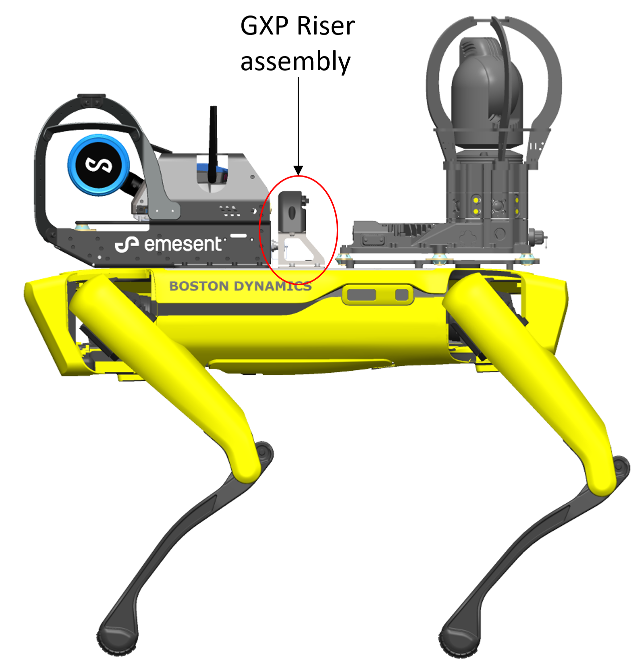
GXP Riser (optional)
The GXP Riser allows a rear-mounted Boston Dynamics payload to be used alongside the Hovermap Spot Cage. Install the riser before attaching the GXP unit.
Parts required
Emesent GXP Riser Kit.
Boston Dynamics GXP with Shielded Ribbon Cable.
Step 1: Attach the risers to the GXP
Remove the front payload port cover if not already removed. If a GXP has been previously attached to that port, remove it. Keep the cover in a secure location.
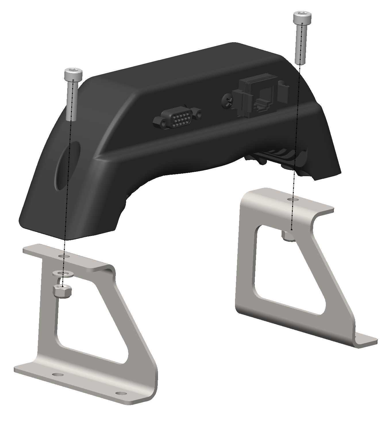
Attach the left and right risers onto the GXP unit using two M5x20 bolts with washers and flange nuts. Use an 8 mm spanner or adjustable wrench to grip the flange nut while tightening. The risers should concave inwards, with the sloped edges on the same side as the GXP connectors (the rear side).
Step 2: Align and secure the T-slot nuts
Insert two T-slot nuts into each payload rail (four total) using the rear cut-out in the payload mounting rail.
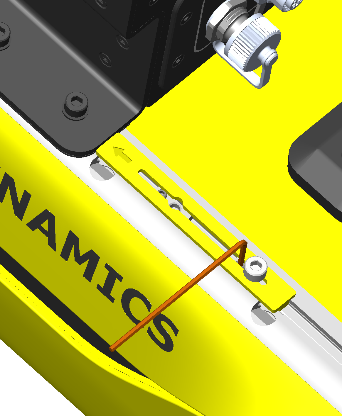
Use the GXP Nut Alignment jig to position the T-slot nuts correctly. Place the alignment tool against the cage within the payload rail channel, with the arrow pointing toward the cage or front of the robot.
Secure the four T-slot nuts using the 2 mm Hex Key.
Step 3: Mount the risers and attach the ribbon cable
Mount the risers to the payload rails using four M5x8 screws.
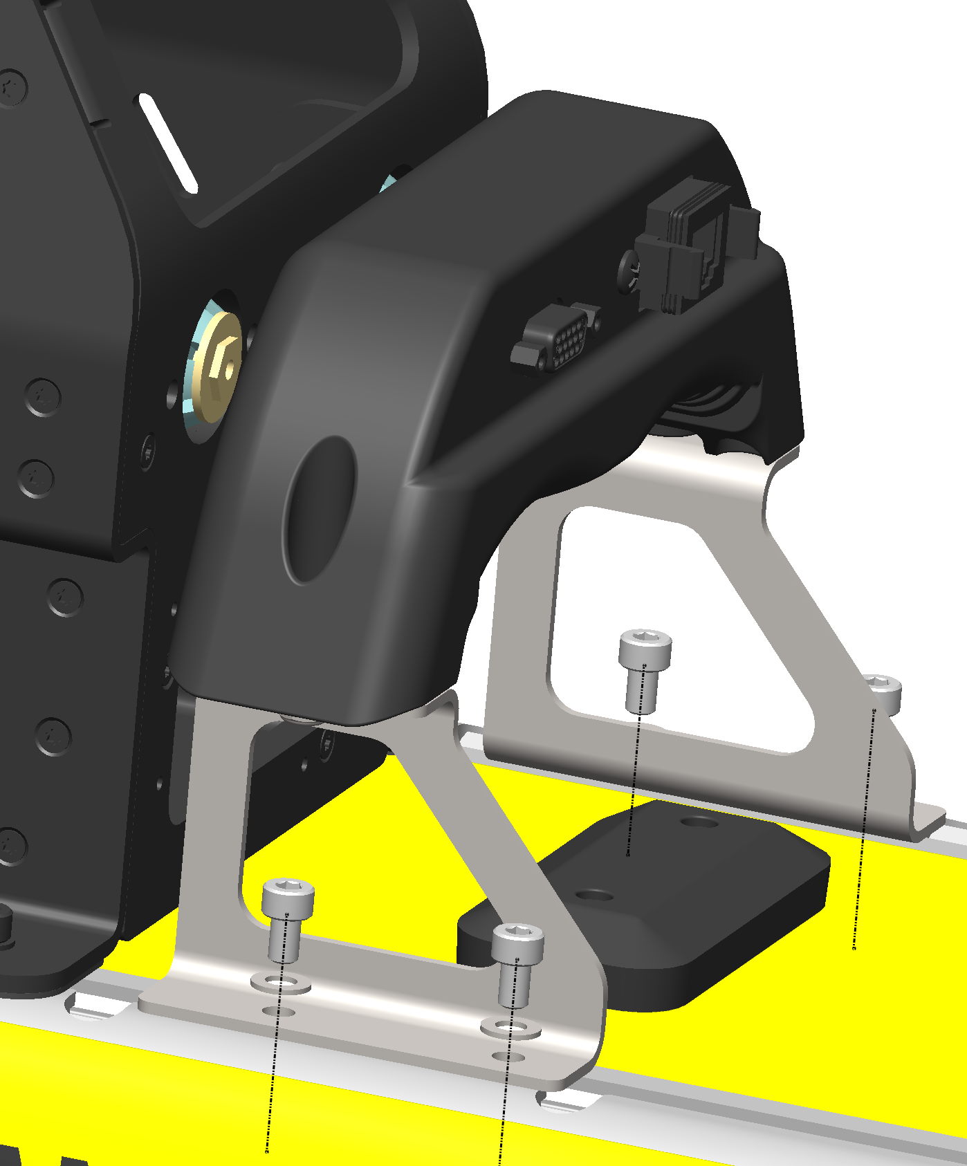
Attach and fasten the ribbon cable to the bottom of the GXP and the robot's front payload port.
Long Range Radio Antenna Extension Kit (optional)
The Long Range Radio (LRR) Antenna Extension Kit allows antennas to be mounted at the back of the Spot Cage for greater communication range compared to the standard antenna mount location.
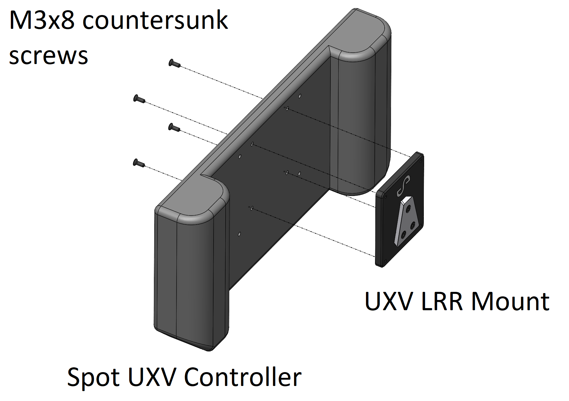
A bracket is included in the kit to allow the Groundside LRR to be mounted at the back of the Spot UXV Controller.
Two antenna kits are available for the LRR: one for the 915 MHz band and one for the 2.4 GHz ISM band. Use an LRR Antenna Extension Kit that matches the frequency band of the LRR hardware. Using a kit with a different frequency band reduces the communication range.
Step 1: Install the antenna
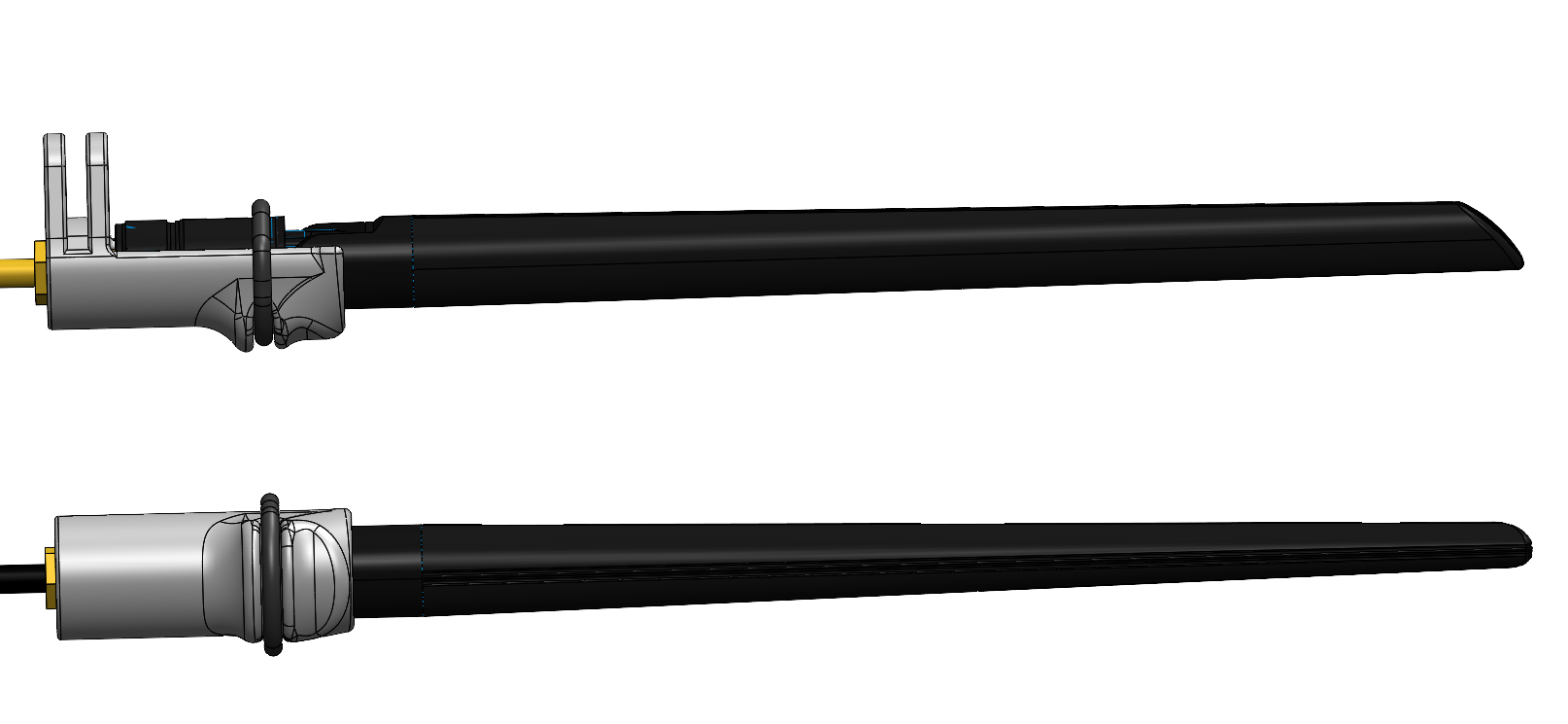
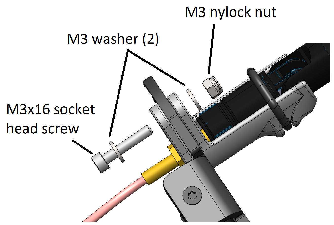
Fully tighten each antenna into the SMA connector of the antenna support elbow and secure it with the supplied o-ring.
Locate the two antenna extension mount holes on the rear of the cage.
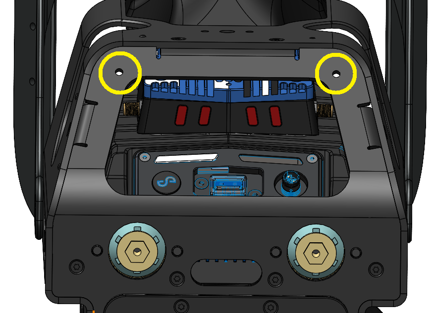
Slide the left-hand elbow support (the "L" and "R" markings are embossed on the inner face) into place on the left-hand side of the rear cage panel until the mounting holes align.
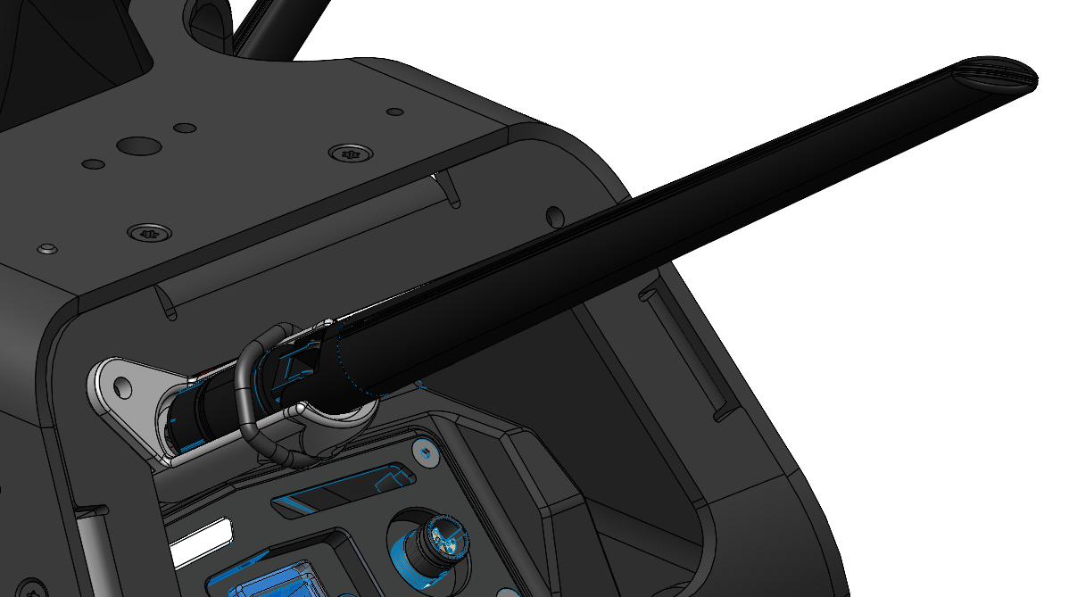
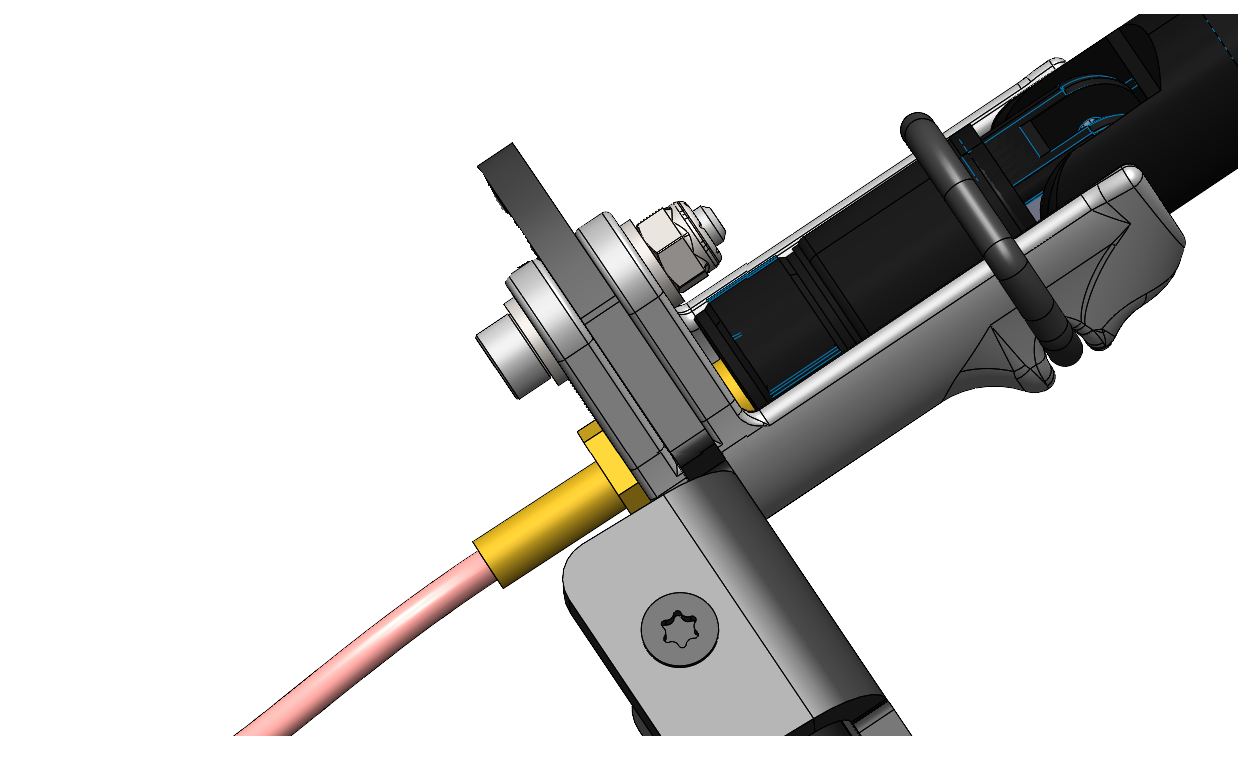
Push an M3x16 socket head screw with an M3 washer through the elbow support mounting flange. Secure with an M3 washer and M3 nylock nut. Tighten until the elbow support material slightly compresses.
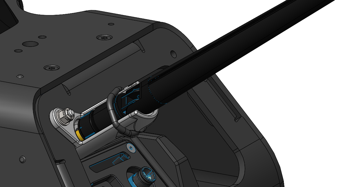
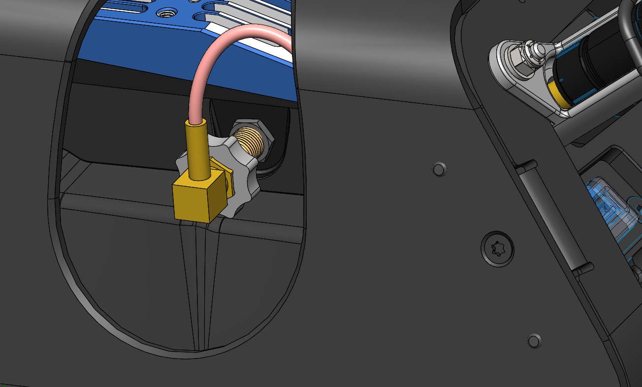
Attach the antenna extension lead to the LRR by tightening the SMA connector using the thumbscrew until finger tight.
Repeat the steps above to install the right-hand side antenna extension.
Step 2: Mount the Groundside LRR
Remove the display tablet from the UXV Tab 3 case.
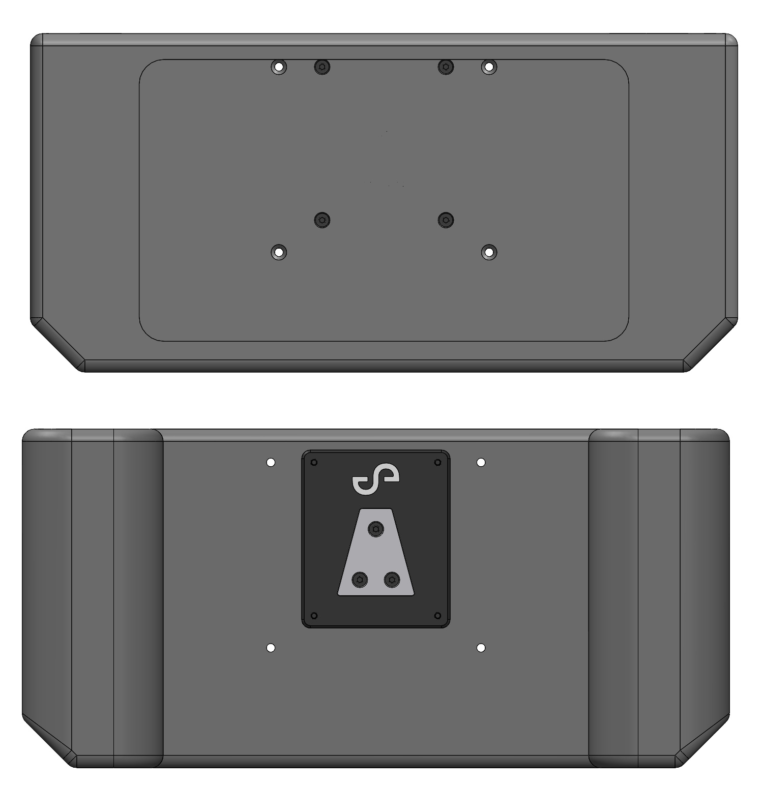
Line up the UXV LRR Mount to the inner UXV Tab 3 case mount holes, with the Emesent logo oriented towards the top.
Attach the UXV LRR Mount to the UXV Tab 3 case using the four supplied M3x10 countersunk screws. Apply Loctite 222 and hand tighten.
Outcome
The Hovermap Spot Cage is installed on the Boston Dynamics Spot, Hovermap is mounted on the cage, and the GXP and any optional accessories (GXP Riser, Long Range Radio Antenna Extension Kit) are connected. The system is ready for configuration and operation.
Related documentation and support
For assistance, contact the regional Emesent partner or the Emesent Client Support team.