
This article explains how to process scan data from an Emesent scanner using Ground Control Points (GCPs) in Emesent Aura to produce an accurately georeferenced point cloud.
Aura supports three types of surveyed point:
Automatic match targets: circular reflective targets that Aura matches automatically to the imported survey data.
User-selected targets: other identifiable features such as checkerboards, paint marks, or natural landmarks, assigned manually.
Check points: surveyed points used for independent accuracy validation.
All surveyed points can contribute to georeferencing the point cloud, improving accuracy and reducing Simultaneous Localization and Mapping (SLAM) drift.
What you will need
Software: Aura 2.0 or later.
Scan data: scan data from an Emesent scanner, with visible targets.
Surveyed targets: at least 3 GCPs (automatic or user-selected), with optional check points.
Survey data: coordinate information for eaminimch GCP, including X (easting), Y (northing), Z (elevation), and the radius for automatically detected targets. Coordinates may be provided in meters or feet. Both US survey foot and international foot units are supported for import.
Procedure
Step 1: Format the survey data
Prepare a CSV file containing the surveyed coordinates for each GCP target visible in the scan. Coordinates can be surveyed before or after scanning, but they must be available before processing in Aura to enable georeferencing and improve SLAM accuracy. Use a suitable survey instrument such as a GNSS receiver or total station.
Save the file as CSV (Comma Separated Values) only, not CSV UTF-8, or Aura may fail to import it.
Create a new CSV (Comma Separated Values) file, or download the template.
Enter one line per GCP target using the structure: ID, X, Y, Z, Radius.
Column | Description |
|---|---|
ID | Unique identifier for the GCP. |
X | Easting coordinate. |
Y | Northing coordinate. |
Z | Elevation. Use a right-handed coordinate system with Z (elevation) defined as up. |
Radius | Target radius in meters. Enter the radius only for flat, circular retro-reflective targets. Leave this field blank for all other target types. Aura only attempts automatic matching when a radius is provided. For Emesent-supplied reflective targets, use 0.125 m for small targets (25 cm diameter) and 0.250 m for large targets (50 cm diameter). |
Example
ID,X,Y,Z,Radius
Reflective_big_1,2736.075,5595.273,27.596,0.250
Paintmark1,1326.747,5388.476,22.041,
Reflective_small_1,1309.543,5141.822,29.607,0.125
Reflective_small_2,1787.757,5270.110,21.275,0.125
Checkerboard1,1818.227,5731.992,28.501,
Checkerboard2,2774.159,5115.728,29.817,
Finalize the CSV file:
Verify column count: each row must contain exactly 5 columns. Entries with a user-selected target must contain exactly 4 columns.
Filter entries: include only the surveyed GCPs that were visible in the scan.
Save format: save the file with a .csv extension.
Close file: after saving, close the file. Leaving it open in Excel may cause issues when importing into Aura.
For easier organization and to avoid errors, store the survey data CSV in the same folder as the dataset.
Step 2: Open Emesent Aura
Open Aura by double-clicking the desktop icon or launching it from the Windows Start menu.
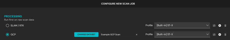
Step 3: Select the processing type
In the Process tab, click + Process Scan in the upper-left corner.
In the Configure New Scan Job panel at the bottom of the screen, select GCP as the scan type.
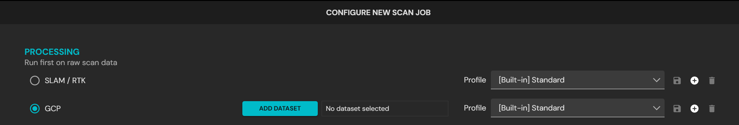
Step 4: Add the scan and survey data
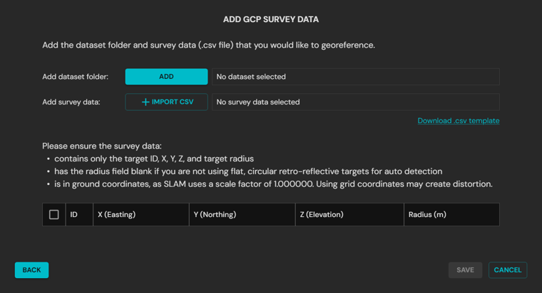
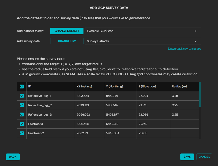
In the Configure New Scan Job panel, click Add Dataset to open the Add GCP Data dialog box.
In the Add GCP Survey Data popup, add both the dataset folder and the survey data CSV:
Add dataset folder: browse to the root folder of the unprocessed scan. Do not select subfolders such as Output/. Always choose the root folder of the extracted scan.
When prompted, select the Scan Environment. Choose the environment that most closely matches the scan. See Aura scan environments.
Add survey data: select the CSV file created in Step 1.
Select the unit of measurement the survey data CSV uses.
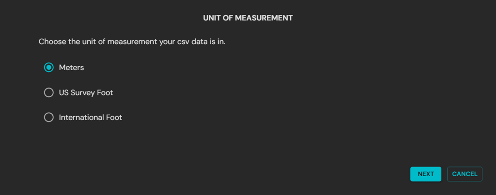
If the CSV file has not been generated, or if the file fails validation, click Download .csv template in the Aura interface to obtain a new template.
Loading an unprocessed dataset into Aura may take time, as Aura validates the dataset based on the scan size.
Step 5: Review the loaded survey data
Aura displays the CSV file in the Add GCP Survey Data popup once it has loaded.
Review the data to ensure it is correct and that the correct file is selected.
Choose one of the following options:
Save: click Save to proceed with processing.
Change CSV: click Change CSV to select a different survey data file.
Step 6: Define the output location
In the Configure New Scan Job panel, locate the Location section at the bottom of the screen.
In the text box beside the Location scan folder path, enter a descriptive name for the output folder.
Verify that both the location and the folder name are correct before continuing.
If no name is entered, Aura creates a subfolder named output by default.
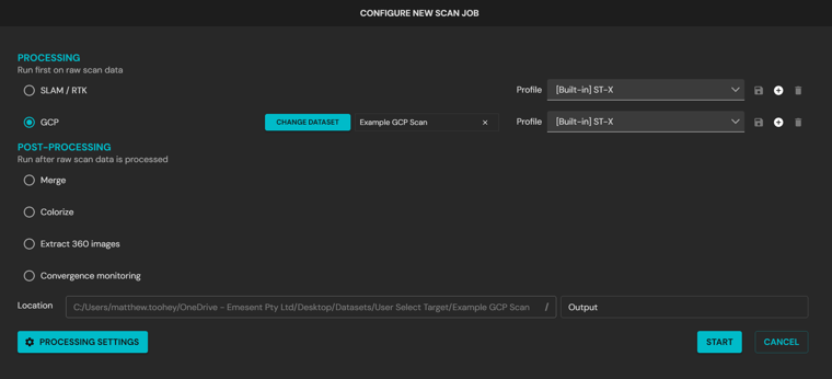
Step 7: Select the processing profiles
In the Configure New Scan Job panel, select a processing profile for SLAM and a processing profile for GCP:
The SLAM profile controls how SLAM data is processed.
The GCP profile controls the settings applied to GCP processing.
For most scenarios, select Standard. See Processing profiles.
On addition of a dataset, profiles may be set automatically based on the hardware used to capture the scan.
If the processed output shows ghosting, misalignment, or duplicated features, select an alternate SLAM profile. If Aura does not automatically detect the expected targets or meet accuracy requirements, select an alternate GCP profile. Choose profiles to suit the scanning environment and mission requirements.
Step 8: Customize the processing settings (optional)
Aura provides several processing settings that can be adjusted when the default profiles are not suitable for the scanning environment or project requirements. These settings are grouped into three tabs: General, GCP, and Output.
In the Configure New Scan Job panel, click Processing Settings in the lower-left corner.

Adjust the General and Output tabs as needed, using the same options as standard scan processing.

Open the GCP tab to refine how targets are detected and processed. See the GCP settings reference below for details on each option.
Click Save to apply changes.
For scans with partial or no automatic match targets, ensure Wait for GCP Target Manual Review remains enabled (default setting). If disabled, Aura skips the manual step and processes the point cloud without GCP correction.
GCP settings
The settings below primarily affect how compatible targets are matched automatically. Target position uncertainty can also affect the accuracy of the processed, georeferenced point cloud.
Option | Description | Use case |
|---|---|---|
Intensity | The expected range of intensity values of the retro-reflective targets. ST-X: 250 to 255. ST/HVM100: 150 to 255. | Use when automatic match targets are not being detected as expected. Narrow or widen the range until reflective targets appear within the detection band. Adjust the band based on the reflectivity of the targets. Widening the band allows Aura to identify more targets but may also pick up additional reflective objects such as bollards, signs, or vehicle mirrors. |
Number of points | The minimum number of points required to detect a target. | Use when auto-detection of targets is inconsistent. Increase the value when false positives are being created in dense scans, as requiring more points reduces the chance of random clutter being flagged as a target. Decrease the value when targets are small or only partially scanned, so Aura can still identify them with fewer points. Increasing the value will cause sparsely scanned targets to be missed, while decreasing the value will increase the number of false positives. The default value is 25. |
Point cloud target noise | The expected noise or thickness of the LiDAR points on the target. | Use when targets appear noisy or when clusters of points around a target are unusually thick. Increase the value if targets are not being detected due to excessive noise or if reflective surfaces appear fuzzy in the scan. Decreasing the value makes detection stricter, which can prevent misidentifying clutter as targets. The default value is 0.02 m (20 mm). |
Target position uncertainty | The uncertainty in the position of the surveyed targets. | Use when SLAM alignment appears over-constrained to the control points or when survey accuracy is uncertain. Increase the value to give Aura more flexibility when fitting the point cloud to survey data (for example, if control points have lower confidence or if overfitting causes distortions in the cloud). Decrease the value when survey control points are highly accurate and should strongly constrain the SLAM alignment. The default value is 0.003 m (3 mm). |
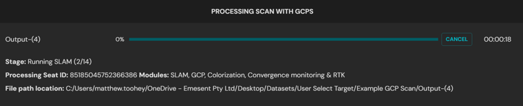
Step 9: Start processing
Click Start in the Configure New Scan Job panel to begin processing.

The Configure New Scan Job panel is replaced with the Processing Scan with GCPs panel. From this panel:
Monitor the progress bar and elapsed time during processing.
Click Retry if processing fails, to restart from the last successful stage.
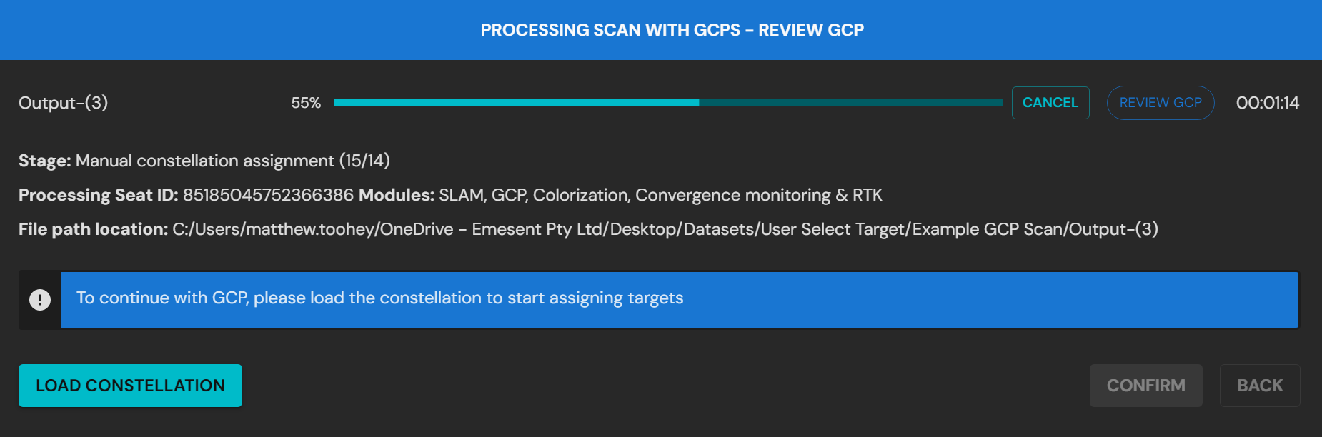
Step 10: Open constellation matching
During processing, Aura automatically detects clusters of points in the scan that resemble circular GCP targets, where a radius has been defined in the survey data. If Review GCP is enabled, Aura prompts a review of the detected GCP targets.
Click Load Constellation to open the intermediate point cloud and the associated constellation file.
(Optional) Once the constellation is loaded, click Reload Constellation to clear any user changes.
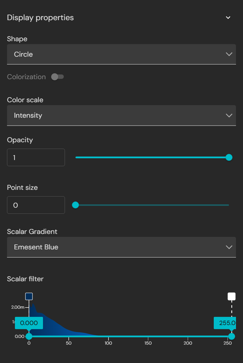
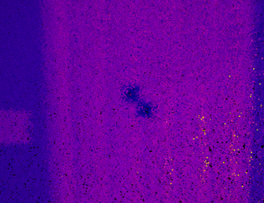
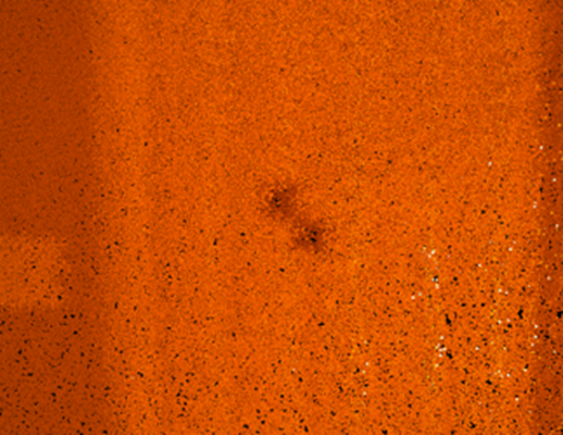
Step 11: Adjust the display properties (optional)
To assist in identifying GCP targets in the point cloud, adjust the Color Scale. Intensity is the most effective option, but other scales such as Time or Elevation can also help narrow point selection.
Example workflow
Scalar Filter controls
|
|
|
|
|
Example: filtering highly reflective targets using the Intensity Color Scale. | ||
.png)
.png)
.png)
.png)
.png)
.png)
|
|
|
Example: displaying variable reflectivity targets using the Color Scale gradient. | ||

Step 12: Match survey points to targets
This step links the survey points from the CSV file to their corresponding targets in the point cloud. It establishes the relationship between the surveyed coordinates and the detected features in the scan, which is critical for accurate georeferencing.
If automatic match targets were detected, they are already assigned. Use this step to confirm the matches and make manual corrections if required.
Navigating to and hiding targets
These options can be used to focus on individual targets when reviewing or correcting assignments.
| Center target: in the Survey Points list, click the center icon to automatically center the viewport on that location. |
| Show or hide target: in the Survey Points list, click the eye icon to hide or display the target in the point cloud. |
.png)
.png)
.png)
There are two methods for assigning user-selected targets.
Recommended method: manual selection
In the Survey Points list, select the survey point to associate with the target using the checkbox, then click Add Target. This automatically opens the Select Point tool.
Use the Select Point tool to left-click near the center of the target in the point cloud.
Refine placement using the keyboard arrow keys.
Click Confirm when the target location is correct.
Repeat the process until at least 3 survey points are assigned, then click Re-Align to align the point cloud with the survey data, making it easier to locate and match the remaining points.
Re-Align also updates the rigid alignment error. Reviewing this value can help identify issues such as incorrect point assignment, mismatched targets, or errors in the CSV coordinates.
.png)
Alternative method: auto-select from filtered points
Adjust the visibility of points so that only the desired target points remain visible.
Use the Select tool to highlight the group of points containing the target.
In the Survey Points list, select the survey point to associate with the target using the checkbox.
Click Add Target. Aura automatically places the target at the center of the selected points.
Refine placement with the keyboard arrow keys.
Click Confirm when the target location is correct.
.png)
Step 13: Complete the target assignment
Continue assigning the remaining survey points to their corresponding targets in the point cloud.
Check the target status in the Survey Points list:
Green box: the target has been successfully associated with a survey point.
Blue box: the target is not associated with a survey point and may need review or deletion.
.png)
Review the list of inactive targets. These are targets that were not successfully matched to a survey point, or that may have been mismatched to an invalid location. Inactive targets do not contribute to georeferencing or alignment until they are reassigned:
If valid, drag and drop an inactive target into the Survey Points list to associate it with the survey data.
Delete the target if it is not valid.
Leave unused if the target is not required for georeferencing.
.png)
(Optional) Mark survey points as Check Points if they should be used only for accuracy validation and not for correcting the scan.
.png)
Review the pre-SLAM rigid alignment error to confirm accuracy and identify any mismatches.
.png)
The reported error values may be large, especially in large or challenging SLAM environments. These values are expected to reduce once SLAM correction is applied during processing.
Step 14: Complete the GCP review
This step finalizes georeferencing by applying the constellation alignment to correct drift and complete the scan.
Confirm all required targets are matched to survey points. Matched points are indicated by a green box and label text.
.png)
Click Confirm. Aura then processes the scan again with GCPs applied to correct drift.
.png)
Once GCP processing is complete, Aura automatically returns to standard navigation mode.
Step 15: View the final output
Once Aura has completed processing, the Processing with GCPs panel is replaced with the Processing with GCPs Complete panel, which provides access to the processed output.
.png)
Review the final output by either:
Opening the files manually from File Explorer, or
Using the View function in the Processing with GCPs Complete panel.
Panel options
Open Folder: opens the scan directory in File Explorer. Inside is the Output folder, or a custom-named folder, containing the processed data.
Files list: each output file includes a View option. Clicking this opens the file in Aura or in the system default external program (for example, a PDF viewer or spreadsheet application).
File | Description |
|---|---|
Processed point cloud | Full-resolution point cloud generated from the processed scan. |
Subsampled point cloud | Reduced-resolution version of the processed point cloud. |
Scan trajectory | Trajectory data of the scan path. |
CSV accuracy report | Accuracy report in .csv format, named after the scan with the date and time of processing. The report describes the correlation between ground control points (GCPs) and point cloud data. Each GCP is positioned within the point cloud data, and the error in X, Y, and Z is determined. The average error of the individual control points is calculated as a Root Mean Square (RMS). |
PDF accuracy report | Accuracy report in .pdf format, named after the scan with the date and time of processing. |
Outcome
The georeferenced point cloud is available in the Viewport for analysis, export, or further editing, with CSV and PDF accuracy reports quantifying the error at each control point.
Additional information
For reviewing and matching detected targets, see GCP Constellation Viewer.
For using surveyed points as independent accuracy checks, see Check Points.
For choosing a processing profile, see Processing profiles.
For reprojecting the georeferenced point cloud, see Reprojecting a processed point cloud.